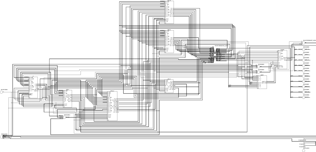
Figure 1: Example/Testbench Schematic
Jeff Heckey
February 21, 2013
In order to provide greater processing throughput and optimize for common, real-world instruction sequences many modern computer processors use Tomasulo's Algorithm. This uses a system of independently operating functional units and dedicated reservation stations to provided out-of-order execution with operation dependencies preserved through register renaming. The reservation stations act as temporary registers. Each functional unit has a single return value bus that is marked with the tag of the reservation station that contained the command. All of the registers and reservation stations monitor these buses for the data that they need autonomously.
This design is simple implementation of the basic concept, consisting of normal registers, two floating-point functional units, load and store functional units a dual instruction dispatch unit, and a completion file for tracking command execution and handling exceptions. The units are tied together with two instruction buses (IB0 and IB1) and a common data bus (CDB) for passing data around. The CDB has a single channel for each functional unit's return tag/data pair, and four channels for distributing register values. A side-band channel, cf, is used for restoring register values after an exception.
All tags and operations are deliberately chosen to be non-zero start values. This eliminates the need for valid bits in the design by simply checking non-zero status in the tag and operation fields.
The variable suffix of 'N' is use throughout the design to denote signals that will be valid during the negative phase of the clock. If this suffix is omitted, the signal is assumed to be valid on the positive phase. Positive edge latched data should only be assigned to signals with an 'N' suffix and vice-versa (some exceptions may occur).
In several logic blocks blocking statements are used to describe logic in more software-like ways, resulting in complicated and non-intuitive logic. This was a design choice to simplify the debug cycle and deliver a functional design in a very short amount of time (~2 weeks). In a normal development cycle, the logic would often appear more complex than in this project, but would be structured to allow for an understanding of the underlying physical logic over the readability.
Since this is a trivial design meant to be completed in a few weeks by a single developer, the design is heavily restricted from a real-life implementation. A few assumptions for the first half of this project are meant to simplify the overall design. The second half will incorporate exception handling with more advanced logic, but several of the assumptions will remain.
No immediate operations are used, except for the addresses in the LOAD and STORE
All buses are full width, though in a real design they can be significantly cut down to limit long wires and routing difficulties with only minimal logic overhead; for example, the CDB returns the full system-level tags for reservation stations (4 bits), when only a valid and an index (2 bits) are necessary.
The following table lists the magic numbers in the system and their meaning.
| Regsiter Tags | ||
|---|---|---|
| R0 | 4 | 4'b1110 |
| R1 | 5 | 4'b1110 |
| R2 | 6 | 4'b1110 |
| R3 | 7 | 4'b1110 |
| Reservation Station Tags | ||
| Adder: A0 | 8 | 4'b1110 |
| Adder: A1 | 9 | 4'b1110 |
| Multiplier: M0 | 10 | 4'b1110 |
| Multiplier: M1 | 11 | 4'b1110 |
| Load: L0 | 12 | 4'b1110 |
| Load: L1 | 13 | 4'b1110 |
| Store: S0 | 14 | 4'b1110 |
| Store: S1 | 15 | 4'b1111 |
| OP CODES | ||
| FADD | 2 | 3'b010 |
| FSUB | 3 | 3'b011 |
| FMUL | 4 | 3'b100 |
| FDIV | 5 | 3'b101 |
| LOAD | 6 | 3'b110 |
| STOR | 7 | 3'b111 |
The Dispatch Unit, or DU, is the heart of this design. It takes up to two instructions per cycle from the instruction queue, performs scheduling based on available reservations stations and provides for register renaming based on tag swapping. The design supports the following operations:
    FADD  dst,  src1, src2
    FSUB  dst,  src1, src2
    FMUL  dst,  src1, src2
    FDIV  dst,  src1, src2
    LOAD  dst,  0,    0,    addr
    STOR  0,    src,  0,    addr
In the positive phase of the clock, the DU will attempt to schedule both instructions based on the availability in the Register Status Unit (regstat). These decisions are then latched.
In the negative phase, the reservations will be updated if they were unable to be assigned due to insufficient reservation stations and if the CDB reported that a reservation station was freed up. If the first instruction is unable to execute, the second will not execute either.
Once the reservations have been determined, the source and destination tags in the results are computed based upon the regstat, the current instructions and the CDB results. For the first instruction a register is remapped if the regstat has already has a mapping for that register and it is not currently present on the CDB. For the second instruction the same rule applies, but if the first instruction's destination is the same as either source register, then the first instruction's reservation tag is used instead. In this case, if the first instruction's reservation is zero, indicating a stall, the second instruction will stalled as well.
Once the tags have been mapped the data is pushed onto the instruction buses in the following formats.
| 50:48 | 47:44 | 43:40 | 39:36 | 35:32 | 31:0 | |
|---|---|---|---|---|---|---|
| Normal: | OPCODE | Reservation tag | Destination tag | Source 0 tag | Source 1 tag | NULL |
| Load: | OPCODE | Reservation tag | Destination tag | NULL | NULL | Address |
| Store: | OPCODE | Reservation tag | NULL | Source 0 tag | NULL | Address |
In the event of stalls, the reservation tags will be zero so no resveration stations will pick up the command. Additionally, the dispatch unit will signal to the instruction queue that the current head of the queue should be held. Instruction 2 will be able to execute ahead of instruction 1 if there are no dependencies between them. Additional checking is performed to ensure that LOAD and STOR addresses are not corrupted.
When an exception occurs, the dispatch unit will stop issuing commands entirely. No attempt will be made to restore the program state.
The Register Status Unit is used to store status of the current address mappings and the busy reservation stations. It updates the mappings every cycle based on the instructions dispatched from the DU and the tags returned by the CDB.
When the CDB returns a tag the corresponding reservation station is marked idle and the rekister mappings are searched to clear any registers that are mapped to that value. Any reservation stations reserved by the DU will then be marked busy (overriding the CDB return values) and any destination registers will be remapped to the corresponding instruction's reservation station.
There are four floating point registers in the design. The register file is in charge of pushing their values onto the CDB when they are requested by an instruction and updating their values when a mapped tag is seen on the CDB.
Since the register file has four channels on the CDB, in order to handle the maximum of four registers requested per cycle (two for each of two instructions), the register file performs no arbitration.
When an instruction is on the bus and the reservation is valid (non-zero) the tag for the destination register is updated with the reservation station's tag. When that tag is seen on the CDB the data is stored in the register and the tag is cleared.
After an exception, the completion file uses the cf_* side-band interface to transfer its shadow register contents on top of the current register contents. This clears the tags and overrides the data, setting it to a clean state.
The reservation stations for the adder and multiplier are fairly simple. They simply monitor the instruction and CDB buses for their ID. The format is shown in the following table.
| 75 | 74:72 | 71:68 | 67:36 | 35:32 | 31:0 |
|---|---|---|---|---|---|
| Busy | OPCODE | Source tag 1 | Source data 1 | Source tag 2 | Source data 2 |
The reservation stations perform all logic operations on the negative phase of the clock. since all data is delivered to the reservation station by the CDB, there is implicitly a delay of half a clock to propagate, leaving only the negative phase for logic.
When monitoring the instruction bus, the reservation station monitors for its ID in the reservation tag. If it is a match, the OPCODE and the source tags are loaded into the reservation station. The CDB is also monitored and the data will be stored and the tag is not set. The busy flag is then set. The CDB is monitored for any non-zero tags and the days is loaded and the tag cleared when there is a match.
Once all of the tags are zeroed, the operation is ready to be performed. The functional unit will then be notified that the command is valid. The functional unit can accept the reservation station on the subsequent cycle which will clear all fields in the reservation station.
The load and store reservations are heavily made of duplicate code from the other reservation stations. The difference is that when an instruction is loaded into a load or store reservation station, the other unit's reservation stations are checked for matches. If they match, the corresponding reservation station's tag is loaded with the instruction to prevent the command from being issued until the previously loaded command is sent. For example: a STORE to address 0x12345678 is loaded into S1; at a later time, L0 receives a read to the same address, at which point the S1 tag is placed into the stall tag for L0; until the completion for S1 is seen, L0 will not attempt to issue.
After adding the Completion File, the store reservation stations had an additional field added for the the PC (program counter) value. In reality, this stores the STOR command's PC minus one. If this matches the completed PC value from the completion file, the store command is executed.
The Completion File (or CF) is used to store all commands dispatch in order. As commands are issued, they are inserted into the CF, a maximum of 2 per cycle to match the dispatch rate. A shadow register file stores the data of commands that have completed in order.
Two pointers are maintained in the CF, insert and complete. The insert indicates where the next dispatch command(s) will be added. This only updates when commands are dispatched to a reservation station. The complete pointer updates when either the next one or two commands have completed. When the completion pointer increments, the shadow register data is updated with the completed data.
The CF will simply add new instructions as they come in until an exception occurs. On an exception, the completion file will mark the exception for the command's entry in the CF. The CF will continue to process completions until the complete pointer reaches the command with the exception. If the exception is for a LOAD or STOR, the complete pointer will halt one command prior to report the last successful command. At this point, the contents of the shadow register file will be transferred over the cf_* bus to the register file. Once the transfer is complete, the CF will report that the system is clean and ready for the OS.
The testbench provides all of the stitching between modules, including IB0, IB1, and CDB. The test bench provides consumer functional units for the floating point ADDER and MULTIPLIER, and LOAD and STORE units.
The ADDER simulates a 4-cycle pipeline and performs an integer addition for simulataion purposes. The MULTIPLIER is a 6 stage pipeline and also uses an integer addition for simulation purposes. The LOAD and STORE functional units each have only one cycle pipelines to simulate a cache hit. The LOAD returns the address as the data for simulation. The STORE unit will only execute STORE operations in order.
Each of these tests are performed by loading instructions into the instruction queue and allowing them to execute in order without other interference.
As a default configuration the value 0x00000000 is stored in R0, 0x11111111 in R1, 0x22222222 in R2, and 0x33333333 in R3. These values are updated in the course of operation and any deviations are noted in the specific tests.
The FSUB and FDIV operations are overridden to generate exceptions. Any LOAD or STOR operations to an address above 0x80000000 will result in an exception.
(hex file)
Four FADD instructions are issued in a row with no register dependencies. The first two are issued immediately. The second two are stalled until the reservation stations are available; since only one reservation station can free per cycle, the last two will execute serially.
(hex file)
Three FADD instructions are issued followed by a FMUL instruction. There are no dependencies between the commands. The first two adds will be dispatched, but the third will stall. The multiply will be dispatched ahead of the third add. All commands will complete.
(hex file)
The register bus can only support 3 register reads in a cycle. All four will be requested in a single cycle and be dispatched in the subsequent two cycles.
(hex file)
The following instruction sequence will be issued to demonstrate a Read-after-Write dependency.
    FADD R1, R3, R3
    FMUL R2, R0, R1
    FADD R3, R3, R2
The dispatched second and third commands will have their register tags replaced with the reservation tags of the preceding command. Two mechanisms are at work, the first is identifying dependencies dispatched on the same cycle, the second dispatched from the register status unit.
The final register values are R1 = 0x66666666, R2 = 0x66666666, and R3 = 0x99999999.
(hex file)
The write-after-read dependency is demonstrated by issuing the following instructions.
    FADD R1, R0, R2
    LOAD R2,  0,  0, 0x12345678
The value of R2 will be updated after being read and no conflict will be observed. The ending value of R1 is 0x22222222, and R2 is 0x33333333.
(hex file)
The write-after-read dependency is demonstrated by issuing the following instructions.
    FADD R2, R0, R1
    FADD R2, R3, R0
    FMUL R2, R3, R1
The value of R2 will be written thrice in order. Only the third write will make it to the registers as the tag will be updated twice on subsequent cycles. The tag will be for A1 for the first dispatch, and then overwritten to M0 for the second. This demonstrates both the simultaneous execution WAW and the delayed WAW dependencies. Only the final value, 0x44444444, will be written to the register file.
(hex file)
Two STOR and two LOAD instructions are issued. The first LOAD is stalled by the STOR to the same address. The second LOAD is allowed to pass the first.
    STOR 0, R0, 0, 0x11111111
    STOR 0, R3, 0, 0x12345678
    LOAD R1, 0, 0, 0x12345678
    LOAD R2, 0, 0, 0x77654321
The values of R1 and R2 will be their corresponding addresses. R2 will be written first, and then R1, showing reordering.
(hex file)
Two LOAD and two STOR commands are issued. The first STOR is stalled by a LOAD, but the second is not stalled. The STOR instructions will not reorder.
    LOAD R2, 0, 0, 0x77654321
    LOAD R1, 0, 0, 0x12345678
    STOR 0, R3, 0, 0x12345678
    STOR 0, R0, 0, 0x11111111
The STOR instructions will be shown to complete in order and stall for the completion of the second LOAD.
(hex file)
Store operations will delay until their preceeding command has completed. This test issues an FADD and a STOR, without an exception.
    FADD R0, R0, R0
    FADD R2, R1, R0
    STOR 0,  R3, 0, 0x12345678
The FADD and STOR will execute correctly, but the STOR will wait until the FADD has completed before executing, despite no other dependencies.
(hex file)
An FADD followed by an FSUB (exception command) are issued. Following that, two LOAD commands are issued.
    FADD R1, R2, R0
    FSUB R2, R3, R3             # Exception
    LOAD R0, 0,  0, 0x77777777
    LOAD R1, 0,  0, 0x44444444
The results should show that R0 is still 0x00000000, R1 is 0x22222222, R2 is 0x66666666 and R3 is 0x33333333. The values 0x77777777 and 0x44444444 should appear and then be removed from the register file. The comp_pc will point to the FSUB instruction.
(hex file)
Issues a mix of LOAD, FADD and FMUL operations to show a page-fault exception. The order is designed to mix register modifications to before and after the exception is executed.
    FADD R1, R2, R0
    FADD R2, R3, R0
    FMUL R3, R0, R0
    LOAD R0, 0,  0, 0x88888888  # Exception
    FADD R1, R1, R1
The register file at R0 is 0x00000000 (original value), R1 is 0x22222222, R2 is 0x33333333, R3 is 0x00000000. The comp_pc will point to the FMUL instruction, not to the LOAD instruction.
(hex file)
Issues a mix of LOAD, STOR, FADD and FMUL operations to show a page-fault exception. The order is designed to mix register modifications to before and after the exception is executed.
    FADD R1, R2, R0
    FMUL R3, R1, R1
    STOR 0,  R0, 0, 0x88888888   # Exception
    LOAD R1, 0,  0, 0x77777777
The register file at R0 is 0x00000000 (original value), R1 is 0x22222222, R2 is 0x22222222 (original value), R3 is 0x44444444. The comp_pc will point to the FMUL instruction, not to the STOR instruction.
(hex file)
An FSUB operation is executed after an FDIV, both of which have exceptions. The FSUB completes first, but the FDIV will cause an exception as well, so the registers should be restored to state after the FDIV, but not the FSUB.
    FADD R1, R2, R0
    FDIV R3, R1, R1             # Exception
    FSUB R2, R2, R2             # Exception
    LOAD R0, 0,  0, 0x77777777
    LOAD R1, 0,  0, 0x77777777
    LOAD R2, 0,  0, 0x77777777
    LOAD R3, 0,  0, 0x77777777
The register file at R0 is 0x00000000 (original value), R1 is 0x22222222, R2 is 0x22222222 (original value), R3 is 0x44444444. The comp_pc will point to the FDIV instruction, not to the FSUB instruction.
This design is still incomplete from a fully working super-scalar design, not having an ALU or some corner cases. Additionally, there are some known issues with timing and dependencies that were not handled. A key omission was checking for address dependencies between same cycle dispatches of STOR and/or LOAD commands. LOAD commands can also preempt the CACHE by loading directly from the STOR reservation station, but that was not implemented either. The CF should be more robust and should not immediately garbage collect, but rather search the completion file for the correct data.
Copyright 2013, Hectic Tech (Jeff Heckey). All rights reserved